The Editor Basics
When creating a new project for the first time, it is recommended to go through the “Guided Tour” to learn the basics of using the PaperVision editor. Click on the “Guided Tour” button when the welcome dialog comes up;
 (1) (1).png)
In this guide, we’ll go into detail through some key points that are mentioned on the Guided Tour.
Input and Output Nodes
The starting two nodes when creating a new project serve as the entry point for your pipeline. The “Pipeline Input” feeds your algorithm with the images from the real-world, ready to be broken down into the steps needed to perform the detection you need.
While developing, you can choose various “Input Sources” to feed your pipeline with, for ease of use. You can use any USB webcam plugged into your computer, while images, videos, and HTTP stream sources are available as well!
The “Pipeline Output”, as the name implies, helps you to visualize the result of your processing. Any image passed onto the output parameter will be promptly displayed when previewing the pipeline.
 (1) (1).png)
Adding More Nodes
.png)
.png)
Click the plus (+) button or press the SPACE key to open the node library. Drag any node into your workspace to add new functionality to your pipeline. Use the gear icon for settings, the play button to run your pipeline, and the code icon to export your pipeline’s source code.
Making Your First Link
To create a link, click and drag from the small circle (the output pin) on the right side of one node, like the Pipeline Input node, and release the mouse button over the small circle (the input pin) on the left side of another node, such as the Color Threshold node.
Note
Pins are color-coded and feature small icons to represent the type of data they carry.
To successfully link two nodes, you simply match the pin colors and icons!
- The visual style of a pin tells you immediately what output it provides or what input it expects.
- For example, the yellow Image pin has a distinctive image icon, while numeric pins represent their data with their own separate visual indicators.
Once you connect matching pins together, the data will seamlessly flow from the output directly into the next processing node.
Running & Visualizing Your Pipeline
Main Pipeline Output
The most important node for visualization is the Pipeline Output node (found in the FLOW category).
- Connect the Final Image: Ensure the final processed image stream is connected to the Output pin of the Pipeline Output node.
- Run the Pipeline: Press the Play button in the bottom toolbar.
The image connected to the Pipeline Output node will automatically be displayed as a live stream in the dedicated preview window (typically located on the top left of the workspace).
Visualizing Intermediate Steps
During development, you often need to check the image at an intermediate stage (e.g., to confirm your Color Threshold settings are correct before contour detection).
- Any output pin that can be visualized (like image pins) has a small Pre-visualization (Previz) button next to it, it is typically represented with a clickable “Eye” button.
- Click this button on the output pin of any node in the pipeline.
Input Sources Menu
The Input Sources menu is what you use to select the data feed for your entire pipeline. It appears specifically when you click the Play button in the toolbar to start processing.
.png)
This menu is crucial because it allows you to choose exactly what feeds the initial Pipeline Input node:
- Image Files: Static images (like PNGs or JPGs) are ideal for testing and debugging as they provide a consistent, unmoving image.
- Live Camera Feeds: Any connected webcam (e.g., “Logi C270 HD WebCam”) is available for live operation, processing a continuous video stream.
Note
You can add new sources by clicking the “Create new input source” button at the bottom of the menu.
Ensuring the Node Flow is Complete and Valid
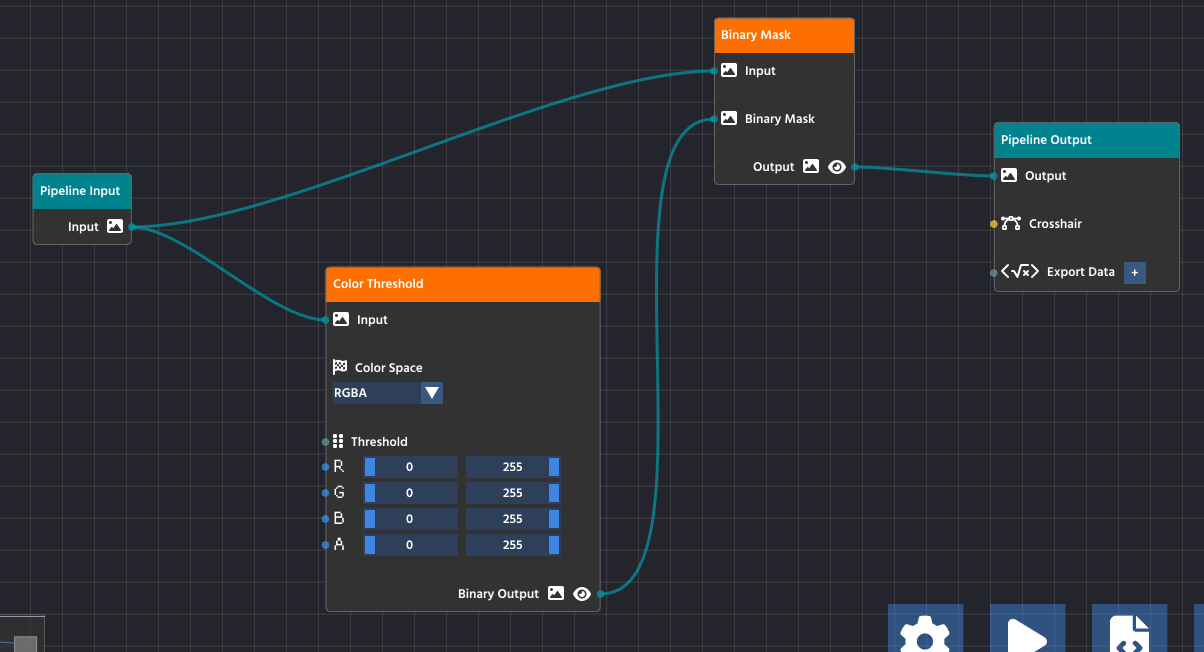
For your pipeline to run successfully, data must flow seamlessly from the input all the way through to the output, and all processing steps must be properly configured. A valid and complete pipeline will always follow this pattern:
- Pipeline Input: All processes must start from the Pipeline Input node, which serves as the entry point for the image or video stream.
- Processing Chain: Intermediate processing nodes (like Color Threshold and Binary Mask) take data from a previous node’s output and pass their processed result to the next node’s input.
- Pipeline Output: The final node in your chain must connect its processed data to the Pipeline Output node. This teal-colored node is the exit point for the processed image, making it available for viewing in the preview window (the
Outputpin) or for exporting (theExport Datapin).
Caution
Crucially, ensure that all nodes in the chain have their required parameters connected.
In the case of the Color Threshold node, this means the image data is connected to its Input pin, but it also means that the threshold values (R, G, B, A sliders) are set either manually or are connected to another node’s output to control the processing logic. A node with an unconfigured or unlinked required parameter will stop the pipeline from functioning correctly.
If your pipeline runs but produces no results, double-check that every node is connected and that the final processed image is successfully routed to the Output pin on the Pipeline Output node.
This article was last modified...
On 2026-03-21 01:07:14 -06:00
By Sebastian Erives
See it here:9f222a6ce64832a9c20251660c897366ca06ec74